|
Temperature dependent electrical properties of Au/Bi/p-Si Schottky junction
Professor Hao-Hsiung Lin's Laboratory
Graduate Institute of Photonics and Optoelectronics, National Taiwan University
臺灣大學光電所 林浩雄教授
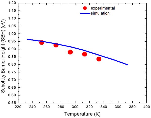
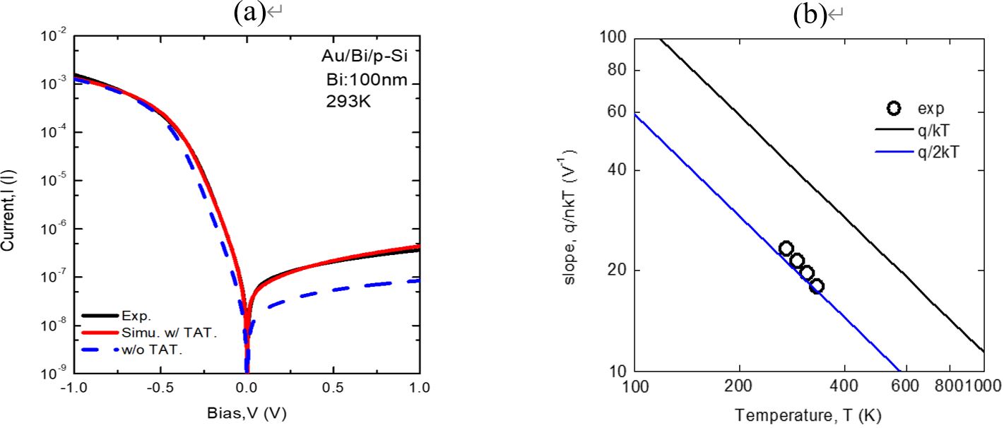
Due to the suppression of metal-induced gap state (MIGS) resulting from the semi-metal property of Bi, ultralow Bi/MoS2 contact resistance and nearly pinning-free Bi/Si Schottky junction have been reported recently [1, 2]. In this research, we employed MBE technique to deposite a 100-nm-thick Bi thin film on low doped p-Si (111) substrates and fabricated Au/Bi/p-Si diodes. Temperature-dependent C-V and I-V methods were performed to study the Schottky junction. Fig. 1 shows the Schottky barrier height (SBH) obtained from C-V method as a function of temperature. Simulation curve for ideal SBH with a reported Bi work function of 4.22 eV [3] is also depicted in the figure. In the calculation, temperature dependent energy gap and effective mass of Bi [4] were considered to find the density of states. Charge neutrality condition was then used to find the temperature dependent work function at various temperature. The simulation curve reaches a good agreement to the experimental results, confirming the suppression of MIGS. Because the SBH is close to Si energy gap, the junction current is not dominant by traditional TE current. Instead, the I-V plot shown in Fig. 2(a) reveals a trap-assisted tunneling (TAT) recombination current [5]. The TAT effect clearly enhanced the reverse current. However, the junction ideality factor meets the line of 2kT, as shown in Fig. 2(b), indicating the behavior of generation recombination current.
|
|
|
Fig.1 Bi/p-Si Schottky barrier height as a function of temperature. Work function shift due to the thermal dependent energy gap and effective mass in Bi is considered in the simulation.
|
|
|
|
Fig. 2 (a) I-V plots of a Au/Bi/p-Si Schottky diode at 293K. Simulation curves based on SRH recombination current with and without trap assited tunneling are also depicted for comparison. (b) Slope of forward log I-V plot as a function of temperature. The experimental result fits the q/2kT line, indicating its recombination mechnism.
|
Reference:
[1] P. C. Shen et al., Nature 593, 211, 2021.
[2] S. Matsumoto et al., SSDM extended abstracts 635, 2016.
[3] H. Jupbik, Phys. Rev. 60, 884, 1941.
[4] A. J. Levin et al., Phys. Rev. B 79, 165117, 2009.
[5] G. A. M. Hurkx et al., IEEE 39, 331, 1992.
Development of Quantitative Analysis Algorithm for Skin Optical Coherence Tomography Imaging Using Generative U-Net Model
Professor Hsiang-Chieh Lee
Graduate Institute of Photonics and Optoelectronics, National Taiwan University
臺灣大學光電所 李翔傑教授
This study developed a U-Net machine-learning model incorporating the concept of residual blocks for automatically segmenting the skin surface and DEJ locations based on the Optical Attenuation Coefficient (OAC) computation. Due to potential disturbances from the background noise, hair, or peeling subsequently affecting the automatic segmentation, manual corrections were combined to ensure the accuracy of the image boundaries, establishing a complex database of OCT images with correct skin surface and DEJ segmentation results, and the corresponding OAC and mask images. These databases were used to train two machine learning models based on U-Net architecture for OAC image generation and segmentation. By combining the results from these two models, quantitative analysis of skin tissue structures was conducted, including measurements of epidermal thickness, optical attenuation coefficients, and skin roughness. Finally, statistical methods were used to validate the similarity between the model training outputs and the expected target analysis data, thereby proving the accuracy of the model training. Part of the study results were presented in Mr. Chau-Hsiang Cheng’s master thesis work.
|
|
|
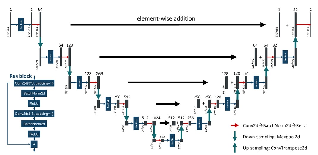
Fig. 1. Architecture of a modified U-Net model, termed U-Net with Residual Blocks. Residual blocks are incorporated into the model, which consists of a total of six layers.
|
|
|
|
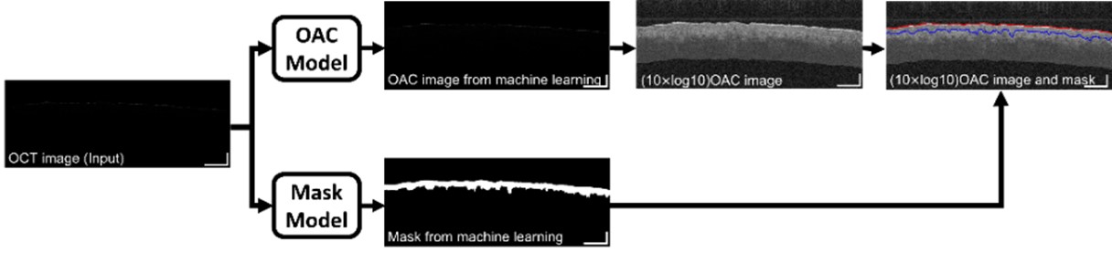
Fig. 2. Training model validation and image post-processing flowchart. Scale bar is 300 µm.
|
|