|
|
|
|
 |
|
 |
| |
|
發行人:吳育任所長 編輯委員:曾雪峰教授 主編:林筱文 發行日期:2024.02.29
|
| |
|
 |
|
 本所黃升龍教授榮獲「112年度國科會傑出研究獎」,特此恭賀!
本所3月份演講公告:
| 日期 |
講者 |
講題 |
地點 |
時間 |
| 3/15 |
Erik, Marketing Manager
光程研創 |
待訂 |
博理館
101演講廳 |
14:20~16:00 |
| 3/22 |
徐正池處長
奇景光電 |
待訂 |
博理館
101演講廳 |
14:20~16:00 |
| 3/29 |
洪健翔經理
台灣超微光學 |
商用光譜儀的設計與應用 |
博理館
101演講廳 |
14:20~16:00 |
|
|
|
|

|
|

|
|
| |
|
|

|
|
Development of an automatic analysis algorithm for the quantitative assessment of the human skin with a portable optical coherence tomography system
Professor Hsiang-Chieh Lee
Graduate Institute of Photonics and Optoelectronics, National Taiwan University
臺灣大學光電所 李翔傑教授
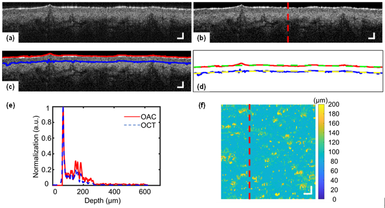
Optical coherence tomography (OCT) enables noninvasive, real-time, and volumetric imaging of skin architectures. In this study, we collected skin OCT images from different human body sites of 25 subjects with a prototype, portable spectral-domain OCT system. The contrast of the OCT images was effectively adjusted through optical attenuation coefficient (OAC) computation. This enables the development of a fully automatic segmentation algorithm, providing the parameters including the (i) epidermis thickness and the (ii, iii) roughness of the boundary between epidermis and air as well as epidermis and dermis. Also, the (iv, v) OAC values of the epidermis and upper dermis layer are available. This study demonstrated the quantitative assessment of the human skin with five different metrics aforementioned, which might benefit the implementation of skin OCT imaging in the field of Cosmetology or Aesthetic Medicine.
|
|
|
Fig. 1. Segmentation of skin epidermis using gradient variation rate of optical attenuation coefficient (OAC) (a) Cross-sectional OCT image of left cheek skin of a 32-year-old male. (b-c) Cross-sectional OAC image of (a). The region between the red and blue lines in (c) shows the layer of the epidermis. The green and blue lines in (d) show 3rd-degree polynomial curve fitting lines corresponding to the red and blue lines in (c), respectively. (e) Normalization of OCT and OAC signals from the position of the red dash line in (b), where the OAC signal could enhance the OCT signal. (f) En-face image from the 3D volumetric OAC image indicates the depth distribution, where the red dash line indicates the position of (a). Scale bars of (a-c) and (f) are 100 and 250 μm, respectively.
|
|
|
|
|

|
|

|
|
| |
|
|

|
|
論文題目:具雙閘極結構之空乏型及增強型氮化鋁鎵/氮化鎵高電子遷移率電晶體之電性分析
姓名:林岱頡 指導教授:黃建璋教授
|
摘要
|
|
基於氮化鎵(GaN)高電子遷移率電晶體(High Electron Mobility Transistors, HEMTs)的高崩潰電壓及高電子遷移率之特性,使得氮化鎵高電子遷移率電晶體具有相當的潛力取代現今矽基材(Si)高頻高效率之電源轉換器功率元件及應用於發展高頻高效率電源轉換器。本論文主要著重於開發具雙閘極結構之空乏型(Depletion mode, D-mode)及增強型(Enhancement mode, E-mode)氮化鎵高電子遷移率電晶體及探究元件可靠性相關之議題,包含元件在高汲極電壓操作下的電流坍塌現象(Current collapse)及在反向導通(Reverse conduction)時的元件行為。
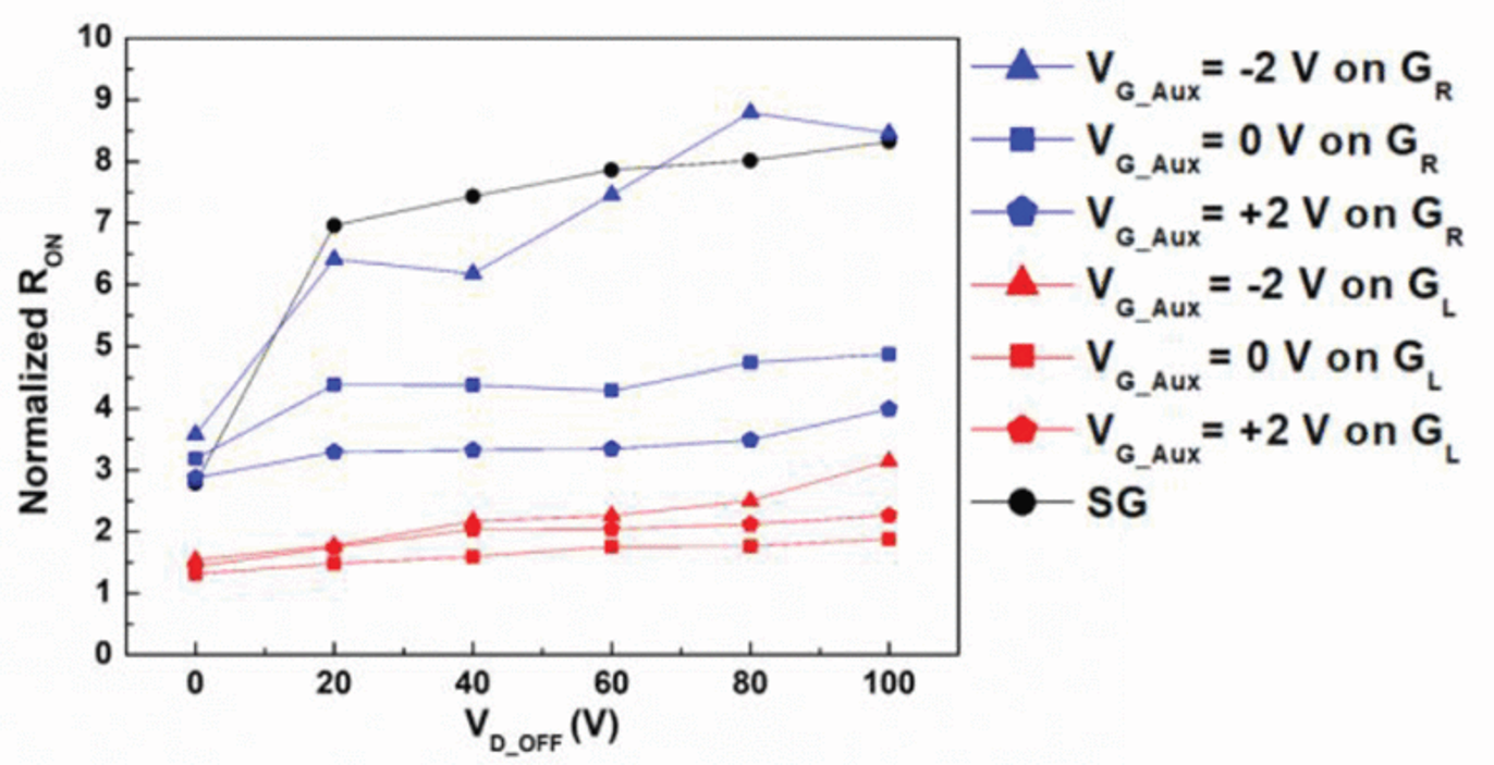
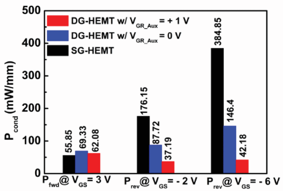
在本文中,我們提出具雙閘極之空乏型氮化鎵高電子遷移率電晶體並藉由施加適當的偏壓在輔助閘極上(Auxiliary gate voltage, VG_Aux),進而在元件關閉時,補償通道中損失的電子以減緩元件動態電阻的上升。此外,基於雙閘極的元件結構,當元件操作在反向導通的條件下時,雙閘極的結構在汲極電極及輔助閘極間提供了一個電流續流路徑。該路徑有助於有效地消除因元件操作在第三象限下所儲存的電荷,從而顯著降低元件整體的操作損耗。
 |
 |
|
圖一、在不同輔助閘極偏壓下,歸一化阻值對汲極電壓之變化
|
圖二、單閘極及雙閘極元件在輔助閘極電壓為0伏與1伏時之正向導通及反向導通損耗估算
|
|
|
|
|
|

|
|

|
|
| |
|
|

|
|
— 資料提供:影像顯示科技知識平台 (DTKP, Display Technology Knowledge Platform) —
— 整理:林晃巖教授、黃茂愷 —
逆向設計的反射器
量子級聯雷射(Quantum Cascade Lasers,簡稱QCLs)因為光波導腔中的次波長尺度光束束縛之影響,固有地會受到輸出耦合不良和高度發散輻射的困擾,因此,QCLs的輸出功率和效率都受到了限制。儘管已經設計了一些架構來解決這個問題,但通常僅限於單波長操作,例如光學頻率梳(optical frequency combs)就不適合使用多波長發射。
現在,來自瑞士蘇黎世聯邦理工學院(ETH Zurich)的Urban Senica和他的團隊提出了一種高效的寬頻太赫茲(THz)QCL,它在2-4 THz的頻率範圍內運作,並生成了一個涵蓋800 GHz的頻率梳。為了提高操作效率,該設備使用了一個逆向設計的端面反射器,以及一個面發射的貼片天線相耦合(出處:APL Photon. 8, 096101; 2023)。這樣可以使該QCL能夠發射高達13.5 mW的輸出功率,約高於傳統設計設備的7倍。
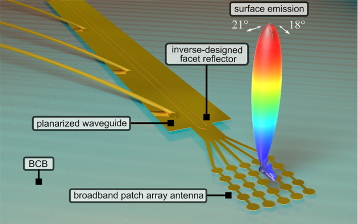
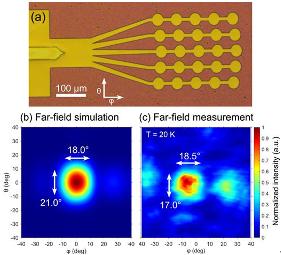
這個QCL基於一個GaAs/AlGaAs異質結構,長2.5毫米,寬40微米。為了減少鏡面損耗,QCL的端面經過逆向設計的方法特別塑造成一個特殊的形狀(如圖一所示),使得反射率從70%降至5-20%(如圖二所示)。在端面的部分反射後,光學模式被引導到一個無源波導中,然後耦合到一個面發射的貼片天線。隨著傳播的光波擴散到天線分支,個別的貼片在相位上振盪,並且組合產生一個窄的垂直光束。寬帶貼片陣列天線被優化為發射光譜在約2.3-3.3 THz之間,像是反射器結構就可以匹配相同的頻段頻率範圍。為了減小光束的發散度,增加了貼片元件的數量至5×5,以擴大天線發射區域,最終得到一個21º×18º的光束(如圖三所示)。
|
|
|
圖一、製作的裝置示意圖:在平坦化的脊型波導的前側是一個逆向設計的端面反射器,該反射器與連接到用於表面發射的寬帶貼片陣列天線的無源波導相耦合。在天線結構的頂部,有一個模擬的寬頻遠場模式的球形圖,該模式與第三(b)圖中相同,其中包含了測得的發射光譜的遠場模擬。發射的光是線性極化的(與脊型波導對齊)。
|
|

|
|
圖二、(a)–(c) 乾蝕刻的逆向設計端面反射器的掃描電子顯微鏡(SEM)圖像,其設計端面反射率分別為5%、10%和20%。隨後,使用BCB(苯基胺)進行波導平坦化,並沉積了擴展的頂部金屬化層和天線提取器。(d) 裁剪端面、平坦化端面和平坦化逆向設計端面的模擬反射率,其中模擬反射率與目標反射率非常匹配。
|
|
|
|
圖三、(a) 平坦化的脊型波導前側的光學顯微鏡圖像,透過一個無源波導將逆向設計的端面反射器耦合到一個表面發射的寬帶貼片陣列天線。(b) 寬帶遠場模擬的發射場形,產生了單葉模式的圖案。(c) 寬帶設備的遠場測量與模擬非常吻合,具有(17.0°×18.5°)的FWHM光束寬度。
|
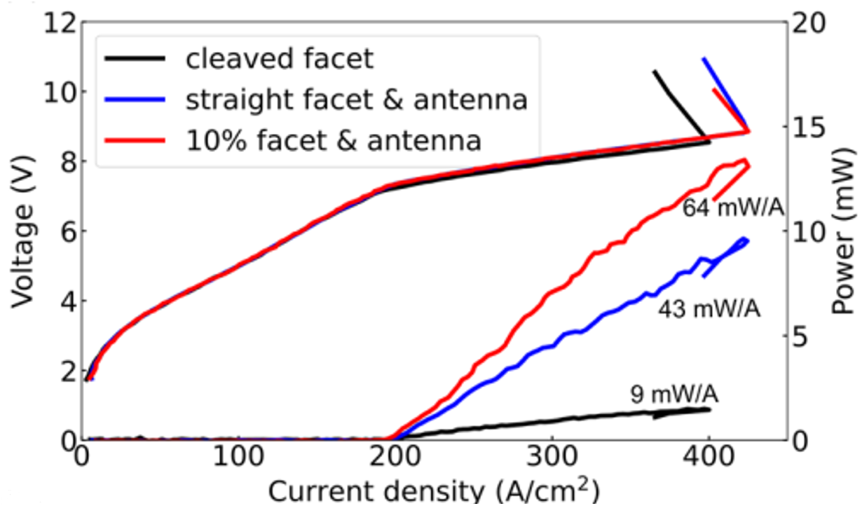
如圖四所示,當該裝置在20K時以500 ns的脈衝和20%的工作週期進行電力驅動時,獲得了64 mW A–1的斜率效率。因此,峰值功率增加到了13.5 mW,比切割端面參考樣品高效率了7.1倍。
|
|
|
圖四、不同裝置的效益比較圖
|
|
參考資料:
|
Horiuchi, N., "Inverse-designed reflectors," Nature Photonics 17, page 933 (2024)
https://doi.org/10.1038/s41566-023-01322-w
DOI:10.1038/s41566-023-01322-w
|
|
參考文獻:
|
Urban Senica, et al., "Broadband surface-emitting THz laser frequency combs with inverse-designed integrated reflectors," APL Photonics 8, pages 1~7 (2023)
https://doi.org/10.1063/5.0163337
DOI:10.1063/5.0163337
|
|
|
|
|
|
|
|

|
|

|
|
|
|
 |
|
 |
|
|
|
|